- Empty cart.
- Continue Shopping
Multi-way switching: Compare wiring and app control
- Posted on
 Strong Digital
- 0
- Categories: Uncategorized
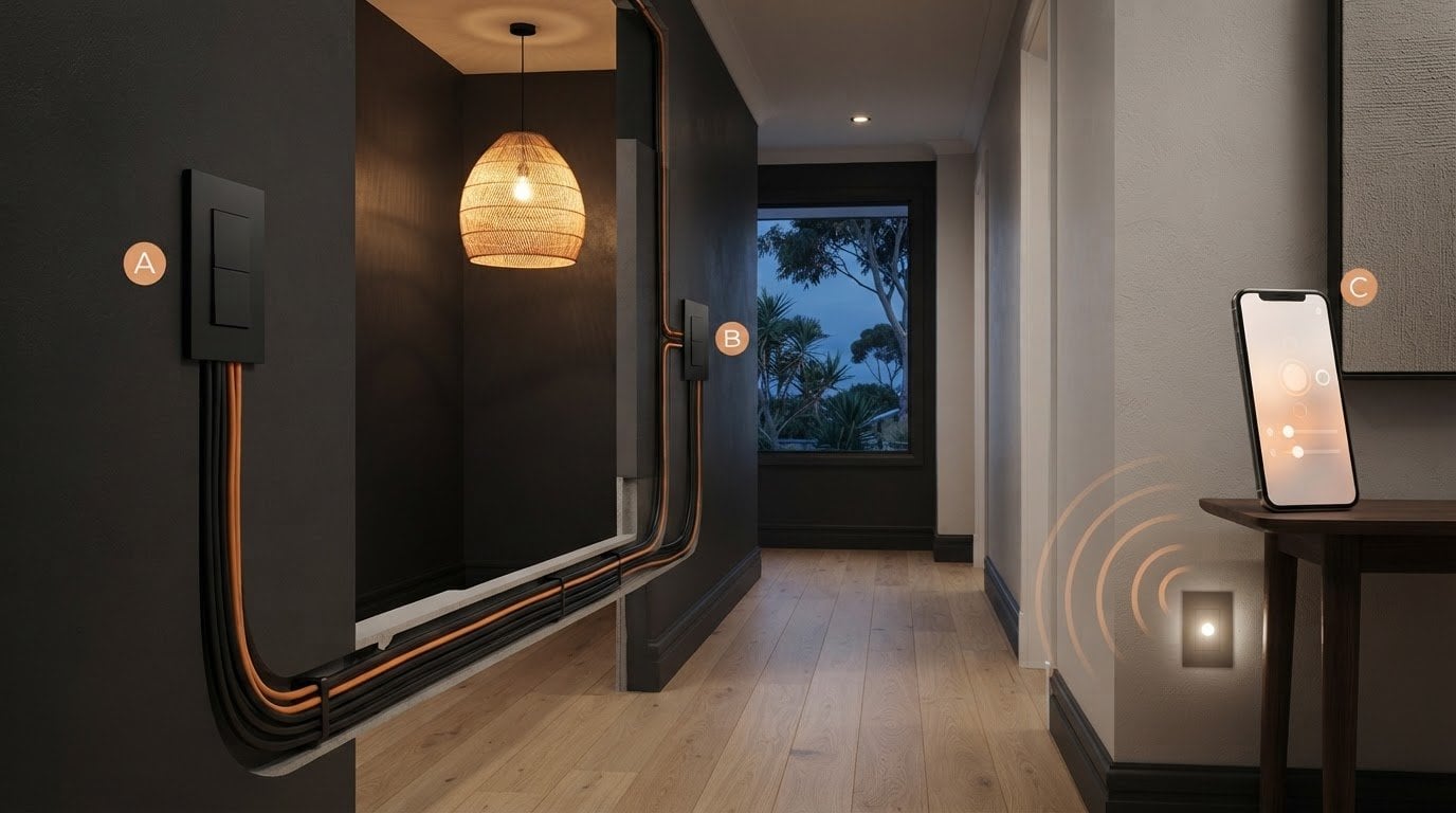
One light can be controlled from more than one location, using wired switches or a wireless control system. Creating multi-way switching means connecting two or more switches to control an electrical load; for two locations, two switches are required. To add more locations, the system needs intermediate switching or another suitable control method.
It’s easy to assume app control simply replaces wall switches. In practice, wired and app-based systems have different requirements. The existing wiring, number of control points and chosen system all affect what will work. App control also requires compatible switching equipment and a control system that supports it.
This guide compares common switch configurations, explains how wiring and app requirements differ, and outlines what to consider for a retrofit or new build. Use it to assess which setup suits your space and how you want to control its lights or other electrical loads.
Key Takeaways
- Compare wired and wireless control by looking at the existing wiring, the number of control points and whether app operation is needed.
- Understand how intermediate switches extend control beyond two locations, and why switch terminology can vary between countries.
- For a retrofit, wireless switching modules can work with existing switches and lights without rewiring; a new build offers more opportunity to plan the setup from the start.
- Match the switching approach to the load and layout, then explore which control option best fits the space.
Comparing wiring and app requirements
Traditional traveller wiring connects two switches with two traveller wires. Changing either switch changes the circuit, allowing one light to be controlled from either location. To add another control point, an intermediate switch goes between the end switches. A six-terminal double-pole, double-throw switch can be adapted with external wiring for this role. The correct connections depend on the switch design, not simply its terminal count.
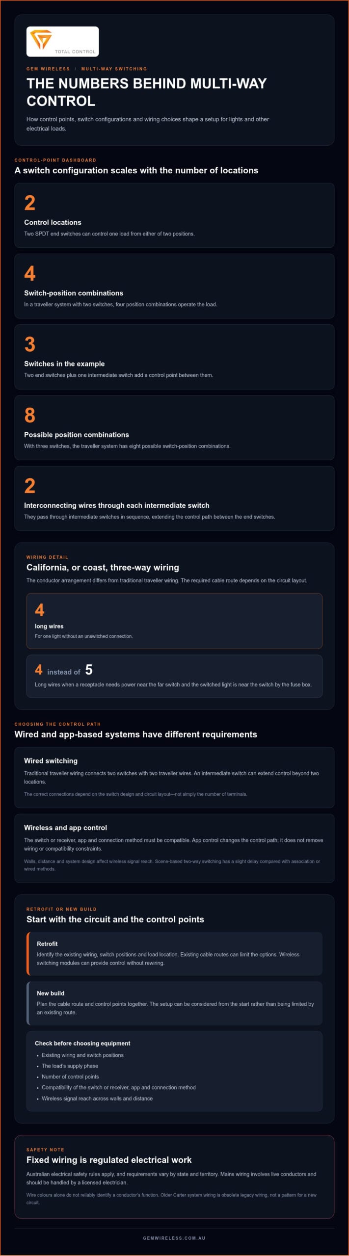
California, or coast three-way wiring, uses a different conductor arrangement. For one light without an unswitched connection, it uses four long wires. If a receptacle needs power near the far switch and the switched light is near the switch by the fuse box, it uses four long wires instead of five. This can affect cable-route planning, but the arrangement must match the actual circuit layout.
App control changes the control path, not the need for compatibility. The switch or receiver, app and connection method must work together. For a retrofit, identify the existing wiring and the load’s supply phase before choosing equipment. In a multi-phase installation, the control arrangement must suit the phase supplying the load. Wireless control also has a practical range limit: walls, distance and system design affect signal reach. An app does not remove wiring or compatibility constraints.
Older homes may have Carter system wiring, an obsolete arrangement that should be treated as legacy wiring, not used as a pattern for a new circuit. Its presence can affect which modern switching approach is suitable. Before choosing traveller wiring or app-based control, identify the conductors, switch positions and load location. In a new build, plan the cable route and control points together. In a retrofit, the existing route often limits the options. Identifying the wiring is a useful first step in creating multi-way switching.
Controlling lighting and other electrical loads from multiple locations
Multi-way switching lets two or more interconnected switches control one electrical load from different positions. The arrangement determines how the switches connect to the load and to one another.
Control from More Than Two Locations
Two SPDT switches can control a load from two locations. In a traveller system, four switch-position combinations operate the load. Examples of electrical loads that can be controlled this way include lights, fans, pumps and heaters.
To add another control point, a DPDT intermediate switch sits between the two end switches. Two interconnecting wires pass through each intermediate switch in sequence, extending the control path. This looping arrangement lets each switch change the load’s state without requiring a separate direct connection from every switch to the load.
App-based multi-control association links compatible controls to the same load or receiver. Scene-based two-way switching has a slight delay compared with association or wired methods, which may matter when an immediate response is preferred.
Safety, Legality and Installation Risks
Australian electrical safety rules govern work on fixed wiring, and requirements vary by state and territory. Switch Module Kits from Gem Wireless provide wireless control without rewiring, so they can be an option when you want to add a control point without altering fixed wiring. Mains wiring work is different: it involves live conductors and should be handled by a licensed electrician.
Common wiring mistakes include confusing traveller and common terminals, mixing conductors, or using a switch configuration that does not match the circuit. Incorrect connections can cause unreliable operation or electrical hazards. Wire colours alone do not reliably identify a conductor’s function.
Installation cost depends on the number of control points, the existing circuit, access to wiring and whether new cable routes are needed. A retrofit with accessible wiring differs from running new cable through finished walls, so the work involved matters more than the switch count alone.
For a system using wireless control, wireless switching modules can provide an alternative to adding traveller wiring between control points.
Three-way and four-way switch configurations
Switch names differ between Australia and the United States. Focus on each switch’s role in the circuit: the number of control points determines the configuration.
Two-Way and Intermediate Switching
In Australia, two-way switches control a load from either of two locations, while an intermediate switch adds another control point between them. This distinction helps you describe the setup when planning a lighting circuit. In United States terminology, a typical three-way switch is a single-pole, double-throw switch. The names differ, but both arrangements allow control from multiple positions.
With three switches, the traveller system has eight possible switch-position combinations. The intermediate switch changes how the connections pass through, so each switch can still control the same load. The circuit layout, not just the switch labels, determines which components are needed.
Diagrams for Multiple Switches
A diagram for one light controlled from three or more switches shows two end switches with one or more intermediate switches between them. This makes the sequence and connections clear before installation. For three switches, the intermediate switch sits in the traveller path between the end switches.
Use a diagram that matches the actual switch type and circuit arrangement. A United States four-way intermediate switch has four external terminals, but terminal layouts can vary by device. A drawing for a different configuration may not accurately represent an Australian installation.
Parts and Switch Types
A wired setup for multiple locations uses two end switches, an intermediate switch for an added control point, connecting conductors and the controlled load. A DPDT intermediate switch can sit between the end switches to control a load from three or more locations. Each added control point affects the circuit layout.
For app-based control, components must support the chosen control method and work together. Choose them by their electrical function and circuit design, rather than assuming switches with similar names are interchangeable.
Installation Steps
Installation involves matching the circuit design, switch types and connections, then checking that each control point operates the intended light. A diagram alone cannot show whether the existing wiring matches the planned arrangement.
- Map the control points and identify the load.
- Have a licensed electrician assess the existing circuit and select a matching configuration.
- Have the electrician install and test the switches and connections.
Leave mains wiring work to a licensed electrician. This overview is not a wiring diagram or an instruction to connect conductors yourself.
Choosing a method for retrofits or new builds
For a retrofit, start by identifying the existing switches, light and wiring route. Then decide whether adding traveller conductors is practical or wireless control better suits the layout. Gem Wireless Switch Module Kits work with existing switches and lights without rewiring, making them an option when new cable routes would disrupt finished walls.
Check the control points and load before choosing a system. A hallway light controlled at both ends may suit wired two-way switching if conductors already connect the locations. If changing the route is difficult, wireless signalling can link control points without extending traveller wiring. The right choice depends on the circuit and installation layout.
A new build gives you more scope to plan switching before the walls are closed. Mark each intended control point, identify the lights or other loads each switch will operate, and coordinate the design with the wiring plan. You can plan a wired arrangement into the circuit or consider wireless control, particularly if the layout may change.
- Retrofit: weigh existing wiring access against the disruption of adding cable.
- New build: plan control locations and cable routes alongside the electrical layout.
- Either project: match the control method to the load, switch points and desired operation.
Wireless and power-line signalling were increasingly used in residential and commercial multi-way switching as of 2012. Low-voltage relay systems typically use 24 V AC for remote momentary switches, while residential use of these systems became rare after an initial burst of popularity in the 1960s. Scene-based two-way switching has a slight delay compared with association or wired methods, so response time may influence the choice.
Compare the options against the actual layout, not just the switch count. Explore wireless switching options when a retrofit needs added control without rewiring.
Gem Wireless: Switch Module Kits
Gem Wireless Switch Module Kits add wireless control to lighting and switching systems. They suit retrofits where you want to add control without rewiring and keep existing switches and lights in use. The right approach depends on the circuit, the load and how you want to control it.
Gem Wireless also offers Mains Powered Switches, Long Range Switches and Switching Modules. These products provide different ways to plan wireless control in residential or commercial settings. Consider which switches and lights you want to control and how the layout affects your setup.
If wireless switching fits your project, visit Gem Wireless to explore its switching options.
Plan control that fits the way you use the space
Think beyond the switch position you need today. A lighting plan should reflect how people move through the room, which loads need independent control and whether the layout may change. This gives creating multi-way switching a practical purpose: making everyday control easier without adding unnecessary complexity.
For wireless switching, Gem Wireless offers Switch Module Kits, Mains Powered Switches and Long Range Switches. These products support different control needs in residential and commercial settings, and work with existing switches and lights without rewiring. Choose an approach suited to the circuit and intended use, rather than adding features you won’t use.
If you’re considering wireless control for a retrofit or new build, contact Gem Wireless to discuss your project. A well-matched setup can make control feel straightforward from the first switch press.
Frequently Asked Questions
How does multi-way switching compare with smart switches or wireless lighting controls?
Traditional multi-way switching connects physical switches through the circuit, while wireless controls send a signal to a receiver. For example, Gem Wireless Switch Module Kits include a wireless transmitter and controller, and work with conventional switch mechanisms. They’re plug-and-play, with no pairing or programming required. This can suit someone who wants to keep familiar wall switches while adding wireless control, rather than replacing them with app-dependent smart switches.
What are the Australian electrical safety rules for installing multi-way switches?
Australian electrical safety rules govern fixed-wiring work and vary by state and territory. Homeowners should not wire mains light switches. Leave that work to a licensed electrician.
How much does it cost to install multi-way switching in Australia?
Installation cost depends on the number of control points, the existing circuit, access to wiring and whether new cable routes are needed.
app controlintermediate switcheslighting controlmulti-way switchingretrofit wiringwired switcheswireless switching