- Empty cart.
- Continue Shopping

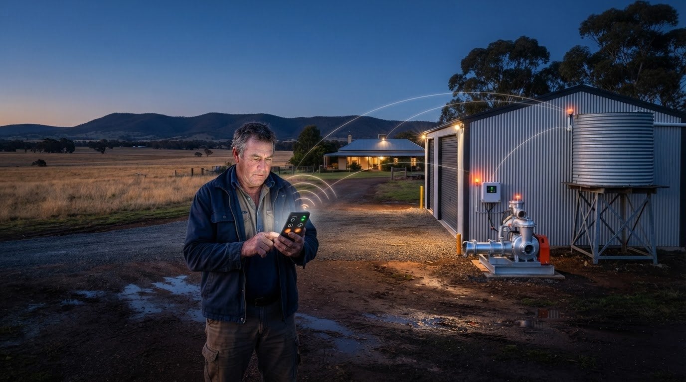
A remote pump control kit lets you start and stop an electric pump from a distance using a switching controller, with some systems also starting or stopping the pump automatically as tank levels change. For high-power irrigation pumps, including 415 V three-phase AC examples, the controller must work with suitable motor-switching equipment. Knowing how to control a water pump remotely starts with matching the control method to the pump and the signal available on your farm.
It makes sense to want control from the house, shed or another paddock, especially when a pump is out of sight. But reliable operation depends on more than a remote command: the pump’s electrical requirements, switching interface and signal coverage all matter.
This guide explains how remote control starts and stops a pump, what cellular or radio coverage must reach the pump, and how to compare irrigation setups. You’ll also learn what to consider when choosing a kit, including whether its switching outputs suit your pump and whether tank-level automation or operating-status signals are useful for your setup.
Key Takeaways
- Remote switching can start and stop an electric pump, while tank-level controls can automate operation as water levels change.
- Choose between cellular and radio control based on the signal path to the pump and the coverage available across your farm.
- Check what each relay output controls, such as pump operation or a fault signal, before choosing a controller.
- Match the control system to your pump’s voltage and motor type; high-current AC pumps may need an interface relay or contactor.
- Explore Gem Wireless Switch Module Kits and switching options when you need a wireless control component for a farm setup.
Remote starting and stopping of electric pumps
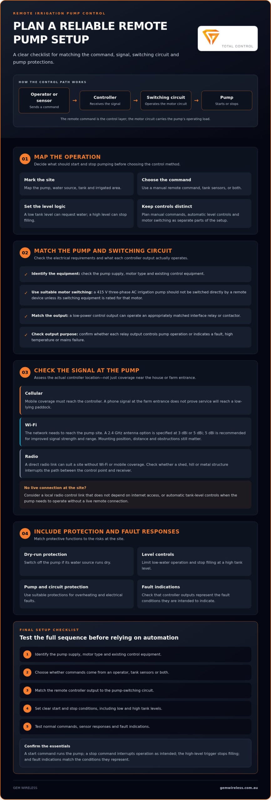
Remote control separates the command from the pump. A signal from a phone, radio unit or automatic sensor reaches a controller, which operates the pump’s switching circuit. You can start irrigation without walking to a pump shed, then stop it remotely when watering is complete. Automatic controls can also start a pump when a tank level is low and stop it when the tank is full.
For a 415 V three-phase AC irrigation pump, the remote device should not switch the motor directly unless its switching equipment is rated for that motor. A low-power control output can instead operate an appropriately matched interface relay or contactor. The control signal then tells the switching equipment when to energise or stop the pump. This distinction matters: the remote command is the control layer, while the motor circuit carries the pump’s operating load.
Plan the operation before selecting or setting up a controller. Map the pump, water source, tank and irrigated area, then decide what should start and stop pumping. For example, a low-level sensor in a storage tank can request water, while a high-level sensor can stop pumping before the tank overflows. A manual remote command offers another way to start or stop the pump when conditions change.
Safety depends on matching protective functions to the risks at the site. Dry-run protection should switch off the pump if its water source runs dry. Level controls can limit low-water operation and stop filling at a high tank level. Suitable pump and control-circuit protections should handle overheating and electrical faults. Controller outputs may also indicate faults, high temperature or mains failure.
A practical setup sequence helps keep the control logic clear:
- Identify the pump’s supply, motor type and existing control equipment.
- Choose whether commands will come from an operator, tank sensors or both.
- Match the remote controller’s output to the pump-switching circuit.
- Set clear start and stop conditions, including low and high tank levels.
- Test normal commands and fault responses before relying on automatic operation.
During testing, confirm that a start command runs the pump and a stop command interrupts operation as intended. Then test each sensor’s response, such as stopping when the tank reaches its high-level trigger. Check that fault indications match the conditions they represent. A clear sequence makes it easier to understand how to control a water pump remotely while keeping manual commands, automatic level controls and motor switching distinct.
Cellular coverage and radio range
Remote control needs a signal path between the operator and the pump controller. A cellular system depends on mobile coverage at the controller’s location, while Wi-Fi requires a network that reaches the pump site. Signal strength at the house may differ from coverage at a pump beside a dam or in a machinery shed. Test the intended installation point, not just the nearest building.
Where cellular service reaches the controller, commands can travel over the mobile network. If coverage drops at the pump, the controller may not receive a remote command. A phone showing a signal at the farm entrance doesn’t prove the same signal will reach a low-lying paddock. Record where a reliable connection is available, then compare that point with the proposed controller position.
A radio link can suit a site without Wi-Fi or mobile coverage, provided the control equipment communicates directly over radio. Position and obstructions matter: a shed, hill or metal structure between the operator’s control point and the receiver can affect the signal path. Walk the route and identify likely obstacles before choosing a location. Don’t assume one radio-range figure will apply across every paddock.
For a Wi-Fi-based setup, an external antenna may help strengthen the signal. The project specifies a 2.4 GHz Wi-Fi antenna with a gain of 3 dBi or 5 dBi, and recommends 5 dBi for improved signal strength and range. Antenna choice doesn’t replace checking the actual signal path. Mounting position, obstructions and distance from the Wi-Fi source still shape the connection at the pump.
If there’s no Wi-Fi or mobile coverage, use a local radio control link that doesn’t depend on internet access, or rely on automatic controls such as tank-level sensors. The right option depends on whether you need commands from a distant location or automatic pump operation at the site.
Use this sequence to assess coverage before settling on a setup:
- Mark the pump, control point, Wi-Fi source and any cellular signal dead zones.
- Test the proposed controller position during the conditions when you’ll operate it.
- Check whether sheds, terrain or metal structures interrupt the direct radio path.
- For Wi-Fi, consider the specified 2.4 GHz antenna options and mounting position.
- Choose automatic level control if the pump must operate without a live remote connection.
For a direct radio-control option, explore Long Range Switches as part of planning a setup for an outlying pump. The key is matching the control method to the actual route between the operator and the equipment, rather than relying on coverage at the farmhouse.
Remote irrigation pump control
A remote irrigation setup links an operator or sensor to pump controls, so irrigation can respond to changing farm conditions. A web app on a laptop, mobile phone or tablet can send commands to the controller. Automatic inputs can also trigger pumping: a low tank level can request water, while a high level can stop filling. These options suit different tasks. Manual control supports decisions made in the field, while level-based control manages routine tank filling.
Start by mapping the water path. Identify the pump, source, storage tank, irrigation area and control point. Then decide what should trigger each action. For example, a tank sensor can request pumping when water is low, while a second threshold can stop filling at the high level. Set out what happens if the operator also sends a manual command. Clear priorities help prevent conflicting instructions from disrupting the planned cycle.
A controller’s outputs can provide operating information as well as control. Depending on its configuration, relay outputs may indicate that the pump is running, a pump fault, high temperature or mains failure. Assign each available output a clear purpose, then make sure its signal reaches the equipment or interface intended to receive it. A running indication confirms operation, while a fault signal can help distinguish a failed start from a normal stop.
Build a straightforward operating sequence before relying on remote irrigation:
- Choose whether an operator, a tank sensor or both can request a pump start.
- Define the stop condition, such as a high tank level or a manual stop command.
- Decide how the controller should respond to a pump fault or mains failure.
- Test each command and sensor input separately, then run a complete irrigation cycle.
Testing should cover ordinary operation and changes in conditions. For a tank-fill setup, confirm that a low-level input requests pumping and a high-level input stops it. Send a manual stop from the web app, then confirm the controller responds. Check whether fault, temperature and mains-failure indications match their assigned outputs. A written sequence helps farm staff understand the intended response without guessing.
In Australia, applicable electrical standards and licensing requirements depend on the state or territory and the work involved. Changes to fixed wiring or mains pump circuits are electrical work and must follow relevant local requirements. Have appropriately licensed electrical personnel handle this work.
Keep the operating plan specific to the irrigation task. A storage tank serving one block needs different start and stop logic from a system supplying several irrigation zones. Record which input requests pumping, which condition ends it and what each output indicates. That simple record makes remote operation easier to follow when someone else takes over the pump.
Remote pump control kits
A remote pump control kit connects a command source to equipment that switches the pump. Compare the control method, relay outputs and compatibility with the pump before choosing a setup.
Remote pump control kit options
Kit configurations vary: one may provide remote switching, while another uses inputs for automatic control or operating signals. Some pump controllers have a single output relay, with its function selected for the task. Decide whether that output needs to control the pump, report a fault or serve another purpose. Then check how the controller connects to the pump’s switching circuit.
Cost depends on the kit’s components, control method, signal requirements and the interface needed for the pump. Installation complexity also affects the overall project. There’s no single price that applies to every Australian farm setup, so compare what the selected system must control rather than judging a kit by its remote function alone.
Safe system installation
Safe installation starts by separating the low-power control signal from the pump’s mains motor circuit. Isolate the pump supply before work, and have a qualified electrical professional handle mains connections. Match the interface relay or contactor to the pump and switching circuit, then secure and protect the control equipment at its installation point.
Before operation, test a start command, a stop command and each control input individually. Confirm that the pump stops when required and that sensor or fault signals produce the intended response.
Check the kit’s electrical compatibility before choosing a configuration. The irrigation pump projects described can use 220 V AC or 110 V AC input power supplies. These figures refer to the controller’s input supply, not an automatic rating for the pump motor. Confirm the controller supply requirements separately from the pump’s voltage, motor type and power rating.
A low-power DC relay output cannot directly operate every high-current AC mains-powered pump. An interface relay or contactor may be needed between the controller and pump circuit. This component converts a control command into switching suitable for the motor load. It also keeps the controller’s output role separate from the pump’s power circuit.
Use this comparison list when reviewing a kit:
- Identify the controller’s input supply and compare it with the available supply.
- Check whether the output relay is single and whether its function can be selected.
- Determine whether the pump needs an interface relay or contactor.
- List the required command types, such as remote start, stop or an automatic input.
- Include installation and signal-path requirements in the project scope.
A kit is a good fit when its control function, supply and switching interface suit the pump setup. For example, a controller with a low-power DC relay output needs an appropriate interface before controlling a high-current AC pump. Treat the complete control path as one system, from the remote command through the relay or contactor to the pump. This makes selection clearer and helps avoid choosing a kit based only on its advertised remote-control feature.
How do I choose a remote pump controller compatible with my pump’s voltage, motor type, and power rating?
Choose the controller by checking two separate circuits: its own supply and the pump’s motor circuit. A controller may accept one supply voltage while controlling a pump with different electrical requirements. Match the controller’s input supply first, then confirm how its output switches the pump. This prevents confusion between the controller’s operating power and the motor’s supply.
The irrigation pump projects described can use 220 V AC or 110 V AC input power supplies. Treat these as controller supply options, not as a blanket rating for the pump. Read the pump’s identification plate and record its voltage, motor type and power rating. Then compare those details with the controller and switching equipment specifications.
Motor type affects the switching method. A high-power 415 V three-phase AC pump needs switching equipment suited to its motor circuit. A low-power DC relay output cannot directly operate a high-current, AC mains-powered pump. An interface relay or contactor can provide the required separation between the controller’s command output and the pump’s switching circuit.
Use a simple compatibility check before settling on a kit:
- Record the pump’s voltage, phase arrangement, motor type and power rating from its identification plate.
- Check the controller’s input supply separately from the pump supply.
- Identify whether the controller output is a low-power DC relay or a suitable motor-switching output.
- Determine whether an interface relay or contactor is needed for the pump circuit.
- Confirm that the proposed switching equipment matches the motor’s electrical requirements.
For example, a controller powered by a 220 V AC supply may still have a low-power DC relay output. That output can send a command, but it doesn’t by itself establish compatibility with a high-current AC pump. The interface equipment must suit the motor circuit. Likewise, matching a controller’s supply voltage alone doesn’t confirm it can switch the pump.
Keep the control function in view, too. A single output relay may have a selectable function, so decide whether it should command pump operation or serve another role. If the system also needs separate run or fault indications, account for those signals when reviewing the controller’s available outputs.
Gem Wireless Mains Powered Switches may suit control applications where a mains-powered switching option fits the setup. Compare the switch’s role with the pump’s circuit, rather than assuming every mains-powered switch can operate every motor. Explore Mains Powered Switches as you plan a control arrangement around your pump’s supply and switching requirements.
Gem Wireless: Switch Module Kits
Gem Wireless offers wireless switching products for farms looking to add remote control to an existing setup. Its Switch Module Kits, Mains Powered Switches, Long Range Switches and Switching Modules support different switching needs. The right fit depends on the pump’s control circuit, electrical requirements and the distance between the operator and equipment.
These products are relevant where the pump can be controlled through a compatible switching arrangement. Gem Wireless systems work with existing switches and lights and require no rewiring, but pump motor compatibility still depends on the switching circuit and any necessary interface equipment. Match the control option to the pump setup before incorporating it into an irrigation system.
Explore Gem Wireless switching products to find an option for your farm’s control setup.
Make your next pump-control decision
Start with one practical question: which pump action would make farm work easier to manage? A clear answer can help you narrow the control setup to the task, rather than adding features you don’t need. If you’re deciding how to control a water pump remotely, let your pump’s switching requirements and the way you operate the site guide your choice.
Gem Wireless offers Switch Module Kits, Mains Powered Switches and Long Range Switches for different switching needs. Consider which option suits your intended control arrangement, then plan how it fits alongside your pump equipment.
Ready to discuss a suitable switching option for your setup? Contact Gem Wireless about pump control and take the next step towards a more manageable farm operation.
Frequently Asked Questions
Why use remote pump control on your farm?
Remote pump control lets you manage irrigation without travelling to the pump each time. For a pump serving a distant paddock, you can send a stop command from your phone instead of making a separate trip. It can also help coordinate watering with a tank’s changing needs. Set clear operating rules and retain a way to respond locally if conditions at the pump change.
What remote-control options are available for water pumps, such as Wi-Fi, cellular, and radio systems?
Wi-Fi uses a local network, cellular control relies on mobile coverage, and radio systems send commands between compatible equipment. A web app can provide access from a laptop, phone or tablet where the controller has a suitable connection. At an isolated pump, compare the signal route and obstacles with the required control distance. Automatic sensor control is another option when operation should respond to water conditions.
How do I set up a float switch or pressure sensor for automatic remote pump control?
Choose a sensor based on what should trigger pumping: a float switch responds to water level, while a pressure sensor responds to pressure changes in the system. Position the float to detect the intended low or high level, or set the pressure thresholds for the pump’s task. Connect the sensor to a compatible controller input, define the start and stop responses, then test each trigger separately before using automatic operation.
Which remote pump control systems are best for farms, rainwater tanks, bore pumps, and household use?
The best fit depends on the pump, water task, signal access and control circuit. A rainwater tank may suit level-triggered operation; a bore pump needs controls suited to its motor and source conditions. A farm pump may need a direct radio link where network access is limited, while a household setup may use available Wi-Fi. Compare the required switching interface and sensor inputs, not just the remote connection.
agricultural technologyfarm automationfarm irrigationremote pump controltank level controlwater pumpswireless switching