- Empty cart.
- Continue Shopping

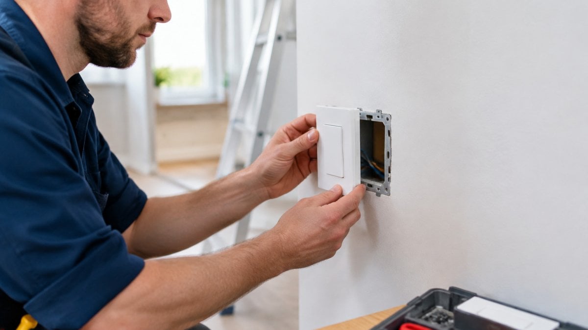
Quick Summary
A wireless light switch sends a radio signal from a wall-mounted transmitter to a receiver at the light fitting, so no cable needs to run back to the switch point. It suits retrofits, switch relocation and rooms where chasing cable is impractical, but it is unsuitable for faulty circuits or clients who need zero battery maintenance.
- Check the receiver’s rated load against the real circuit load, using the LED figure where one is given.
- Confirm LED driver compatibility, including minimum load and any standby current, before quoting.
- Check for a neutral at the switch position, since its absence may force the receiver to the light fitting.
- Isolate the circuit at the switchboard and prove it dead before touching any fitting.
- Test pairing several times, including after a breaker cycle, and record the results on the job sheet.
Table of Contents
- What a Wireless Light Switch Is and Where It Suits a Job
- Pre-Installation Checks: Compatibility and Existing Circuit Assessment
- Isolating Power and Working Safely Under AS/NZS 3000
- Step-by-Step Installation: Receiver, Transmitter and Wall Mounting
- Pairing and Programming the Wireless Switch
- Testing Signal Range and Interference Before Closing Up
- Troubleshooting a Wireless Switch That Will Not Respond
- Booking Your Next Wireless Switch Job With Gem Wireless
- Frequently Asked Questions
What a Wireless Light Switch Is and Where It Suits a Job
A wireless light switch sends a radio signal from a wall-mounted transmitter to a receiver fitted at the light fitting, so the light can be switched without a cable running back to the switch point. You can compare wireless switch kit options and typical installation costs for this setup. For many electricians, it solves the problem of adding control to a room where chasing cable through plaster is impractical or unwelcome.
Wireless switch kits are most useful where the existing wiring cannot easily be changed. Common cases include rented or heritage properties, tiled or glass walls, and rooms where the switch needs to move to a new location. They also suit retrofit jobs where the client wants a second control point without a full rewire.
They are less suitable where the existing circuit is already faulty, or where the client wants a hard-wired, permanent solution with no battery dependency. Know the limits before you quote.
- Good fit: retrofits, switch relocation, two-way control where cable routing is difficult
- Poor fit: circuits with unresolved faults, clients who need zero battery maintenance
Pre-Installation Checks: Compatibility and Existing Circuit Assessment
Most problems with wireless switches start before the first screw goes in. Treat the pre-installation check as a short survey that decides whether the kit suits the job at all, not as a formality after the client has paid a deposit.
Receiver load rating. Read the receiver’s rated load in the manufacturer’s instructions and compare it with the actual load on the circuit, not the nominal wattage on the lamp box. A receiver rated for a resistive load may not be suitable for the inrush current of an LED driver or a fluorescent ballast.
LED and driver compatibility. LED drivers vary in how they respond to a switched live that is interrupted at the receiver rather than at a wall switch. Some drivers have a minimum load below which they will not strike reliably; others hold a small standby current that can leave a lamp glowing faintly or flashing when the receiver is open.
Dimming requirements. If the client wants dimming, confirm that the kit supports dimming and that the receiver is rated for the lamp type and driver on the circuit. Dimming a receiver into a driver that expects a trailing-edge or leading-edge supply can cause flicker, buzz or a limited dimming range.
Neutral availability. Note whether a neutral is present at the switch position. If none is found, this guide to installing a smart switch without a neutral wire explains how to proceed. Many older installations loop the neutral at the light fitting and bring only a switched live and permanent live to the switch, so a receiver designed to sit behind the switch will not have a neutral to work from.
Circuit type and switching arrangement. Identify whether the existing switch is a standard single-pole, part of a two-way arrangement, or an intermediate switching setup. A wireless kit can often replicate two-way control without new cable, but the existing wiring must be understood so the receiver is not left permanently fed or permanently isolated.
Manufacturer instructions and kit revision. Read the instructions for the specific kit revision, not a generic datasheet. Pairing sequences, terminal layouts and load ratings change between revisions, and a kit bought from old stock may not match the online manual. Keep the instructions on the job sheet.
Watch out: do not assume a circuit is sound because the light works. Test the circuit, record insulation resistance and polarity results where your licence and test regime require it, and note any borrowed neutral or shared circuit before you alter anything.
Isolating Power and Working Safely Under AS/NZS 3000
Isolate the circuit at the switchboard before touching any fitting, and prove it dead with a tested voltage indicator (Preventing electric shocks when working in ceiling spaces). Lock out or tag the breaker where the client or other workers could re-energise it.
AS/NZS 3000, the Wiring Rules, sets the baseline for installation work in Australia (Wiring Rules). Check the current edition and the requirements that apply to your licence class. Your state or territory electrical regulator may add conditions, so confirm those too.
Keep all work within your licence. If the job touches the main switchboard or requires an outlet change you are not licensed to perform, stop and bring in the right tradesperson.
Step-by-Step Installation: Receiver, Transmitter and Wall Mounting
Start with the receiver. Fit it inside or beside the light fitting, following the kit’s diagram for live, neutral and switched-live connections. Keep connections tight and tidy, and do not overload the receiver’s rated load.
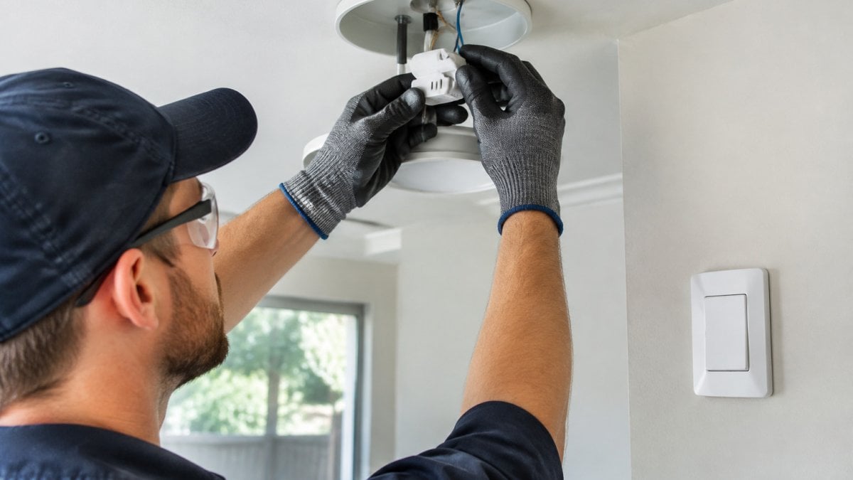
Next, mount the transmitter at the chosen wall position.
Finish by checking that the transmitter sits flat and level. A crooked plate looks poor and can loosen over time.
- Fit the receiver and confirm connections before re-energising
- Mount the transmitter on clean, dry, firm surfaces
- Use screws on tile, glass or metal and adhesive only where it will hold
The article sets out the main installation steps in order, with the key actions for each.
| Step | What to do | Time or frequency |
|---|---|---|
| Fit receiver | Connect live, neutral and switched-live per kit diagram | Before re-energising |
| Check load | Keep connections tight and within rated load | Before re-energising |
| Mount transmitter | Fix at chosen wall position on clean, dry, firm surface | Before closing up |
| Check finish | Confirm transmitter sits flat and level | Before closing up |
| Pair units | Follow kit manual sequence until light confirms link | After power restored |
| Test pairing | Switch from transmitter, then cut and restore power at breaker | Several times |
Pairing and Programming the Wireless Switch
Once power is restored, pair the transmitter with the receiver using the sequence in the kit manual. Pairing usually involves pressing a button on each unit in turn until the light confirms the link.
Test the pairing several times. Switch the light on and off from the transmitter, then cut power at the breaker and restore it to confirm the link survives a restart.
Record the pairing details on the job sheet so the client or a future electrician can reset the link if needed.
Testing Signal Range and Interference Before Closing Up
Test signal range before you close the wall. Operate the switch from the position it will normally be used, then from any other spot the client might use it, such as a bed or doorway.
Interference from other wireless devices can also affect performance. Check the switch in the room while nearby devices are running, and note any dropouts.
Troubleshooting a Wireless Switch That Will Not Respond
Work through faults in a fixed order so you do not replace hardware before you have ruled out the circuit. The sequence below moves from the supply outward: power, then pairing, then connections, then range and interference, then the transmitter and receiver themselves.
Commissioning check before you diagnose. If the switch has never worked reliably, confirm the basics first. The receiver should be powered, the transmitter battery should be fresh, and the pairing should have been completed and tested at least three times, including after a breaker cycle.
Symptom: nothing happens at all. Confirm the breaker is on and the receiver is powered. Check the transmitter battery with a tester rather than by eye. If the receiver has an indicator, confirm it responds when the transmitter is pressed. If there is no response at the receiver, re-run the pairing sequence.
Symptom: intermittent operation. Intermittent faults usually sit in one of three places: a loose terminal at the receiver, a failing battery, or marginal signal range. Isolate the circuit and check the live, neutral and switched-live terminals at the receiver for tightness and for conductor damage. Replace the battery if its age is unknown. Then test range from the positions the client actually uses, not just from the doorway.
Symptom: works close to the receiver but not across the room. This points to range or obstruction rather than pairing. Radio signals weaken through masonry, reinforced concrete, metal stud framing, foil-backed insulation and some tile or glass. Move the receiver or transmitter a short distance and retest before concluding the kit is faulty. Metal back boxes, metalclad walls and consumer units near the receiver can all reduce range.
Symptom: flicker, faint glow or flashing when off. This is usually a compatibility issue rather than a fault. A driver holding standby current, a lamp below the driver’s minimum load, or a receiver not rated for the driver type can all cause it. Check the driver datasheet and the receiver rating before changing parts.
Symptom: works after re-pairing but fails again later. Repeated link loss suggests a battery nearing end of life, a receiver losing its memory after power cycles, or interference from another device. Note the interval between failures; a pattern tied to a particular appliance or time of day points to interference, while a pattern tied to battery changes points to the battery.
Symptom: one switch works, another does not. On multi-switch installations, confirm each transmitter is paired to the correct receiver and that the channels have not been duplicated. Label the transmitters and receivers during commissioning so a later electrician can identify them without trial and error. Clear labelling also helps when tracing pairing and wiring faults across other connected controls, including during smart thermostat installation.
Watch out: do not disturb energised connections while fault-finding. Isolate the circuit and prove it dead before checking terminals, and replace a transmitter or receiver only after supply, pairing, connections and range have each been ruled out.
Booking Your Next Wireless Switch Job With Gem Wireless
For electricians who want a practical retrofit option, Gem Wireless offers wireless switch module kits designed for plug-and-play installation without in-wall rewiring.
Pricing depends on quantity, dates, and delivery, so visit the Gem Wireless website or request a quote for current prices. If you are weighing a wireless job against traditional wiring, a cost comparison of the two approaches is a useful starting point, and a guide to requesting a quote for wireless automation installation explains what to send.
Get in touch with Gem Wireless today to discuss your next retrofit.
Frequently Asked Questions
How do you install a wireless light switch?
Isolate the circuit at the switchboard and confirm it is dead with a tested voltage indicator. Fit the receiver at the light fitting, mount the transmitter or switch plate on the wall using adhesive backing or screws depending on the surface, then pair the transmitter to the receiver following the manufacturer’s instructions. Test every function before restoring power and closing the wall box. Because installation rules and wiring work are governed by AS/NZS 3000, check your local requirements and licence obligations before starting.
Do wireless light switches need a neutral wire?
Whether a wireless switch needs a neutral depends on the specific product and how the receiver is powered. Confirm the requirement against the manufacturer’s installation sheet before quoting the job. Older properties often lack a neutral at the switch position, which is one of the main compatibility checks to complete during the site assessment. For current guidance on a specific kit, get in touch with Gem Wireless.
How do you troubleshoot a wireless switch that will not pair?
Start by confirming the receiver has power and the light fitting is working on the original circuit. Re-run the pairing sequence as documented in the kit instructions, then retest. If the switch still does not respond, check the kit’s installation sheet before assuming a faulty unit.
Can a wireless light switch work with existing lights?
Compatibility depends on the lamp type, the load and the wiring arrangement, so confirm the fitting and any LED drivers against the product specification. Two-way switching and traveller arrangements need particular attention, and a quick check at the existing switch position will usually show which configuration you are working with.

wireless light switchwireless light switch installation tips for electricianswireless light switch troubleshootingwireless switch pairing and programming